SUSPENSION:
THE CABLES & HANGERS

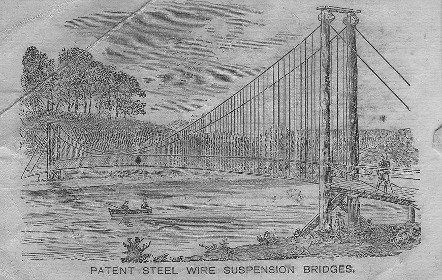
Early Harper bridges had three sections to their main cable. The middle section ran between the masthead tensioners, while the outer anchor cables were fixed at ground level and passed up to a tensioner at the mast head. A drawing of the bridge at Nairn makes this clear. It also emphasises that the bridges cables were of galvanised steel wire rope – which had only recently (1870) become available in quantity.
Occasionally, these anchor cables were fixed to a masthead not by tensioner but by a screw bolt (see Birkhall bridge). In 1893, full main cables appeared, running between anchorages via saddles at the mastheads.
Aberdeen Art Gallery & Museums Collection
The cable core of early bridges was of hemp rope as shown in this one below from Tanarmouth; later, Louis Harper ran cores of steel.

Hangers
The ‘Woggle and Stop’
The hangers (or suspenders) for all Harper bridges were 5/8ths inch steel. The arrangement of their connection to the main and deck cables is shown. The stop was applied to the cable and consisted of a 90% steel ring crimped onto the cable. Whether these were applied before dispatch or on site is not known. The hangers would have been fitted on site and were sent out as separate components. How were they fitted?

Woggle
Hanger standing part
Cable

Woggle
Stop
Louis Harper states in his specification that the hangers were delivered to length +/- 1/16th inch (1.6mm). To achieve this a jig would have to be employed to preform the tight loop for the cable and ensure that the standing part and the tail could be in close approximation in situ, held by the ‘woggle’. We know from photographs that the hangers were attached to the main cables first. Presumably the tail was opened to allow the loop to be placed above the cable and the whole hanger than pulled down so that the cable snapped into the loop. Then the tail and the standing part would have been pulled together and the woggle pushed up forcibly to be seated snug at the neck of the loop. Then the tail would have been bent to the horizontal to keep the woggle in place. The simplest way of doing this would be to slip some iron tubing over the tail, first to ease it open to receive the cable, then to draw it to the standing part, then finally to push the woggle up before bending the tail outwards. It would have been important to ensure all these manipulations didn’t alter the overall length of the hanger.
We can see from photographs of the bridge at Narva and also at Baroda, India (see Building a Harper Bridge), that the first hangers to be connected to the platform cable were those at the centre. One beam was placed transversely across the main cables and another below the platform cables. They were linked by a block and tackle which drew the main and platform cables together. The hanger, already attached to the main cable, would have its lower tail opened as before to receive the platform cable as the block and tackle allowed the two cables to separate in a controlled way. The weight and tension of the platform cable would ensure that it seated within the hanger loop and it would have then been fixed by the woggle as before. (See also Building a Harper Bridge)


The earliest bridge with these features unaltered subsequently can be seen in the wreck of the bridge at Craighall Castle, designed and built by John Harper (although the original Birkhall bridge also had them). All Louis Harper's bridges employed the same technique as illustrated above. The drawings were taken from plans of the Sellack Boat bridge, as is the illustration above.

